Terrain Blending in Unreal Engine 5
Solo | Terrain Blending Shader Guide for Unreal Engine 5
2024-10-28 09:00:00 +0000
Why Use Terrain Blending?
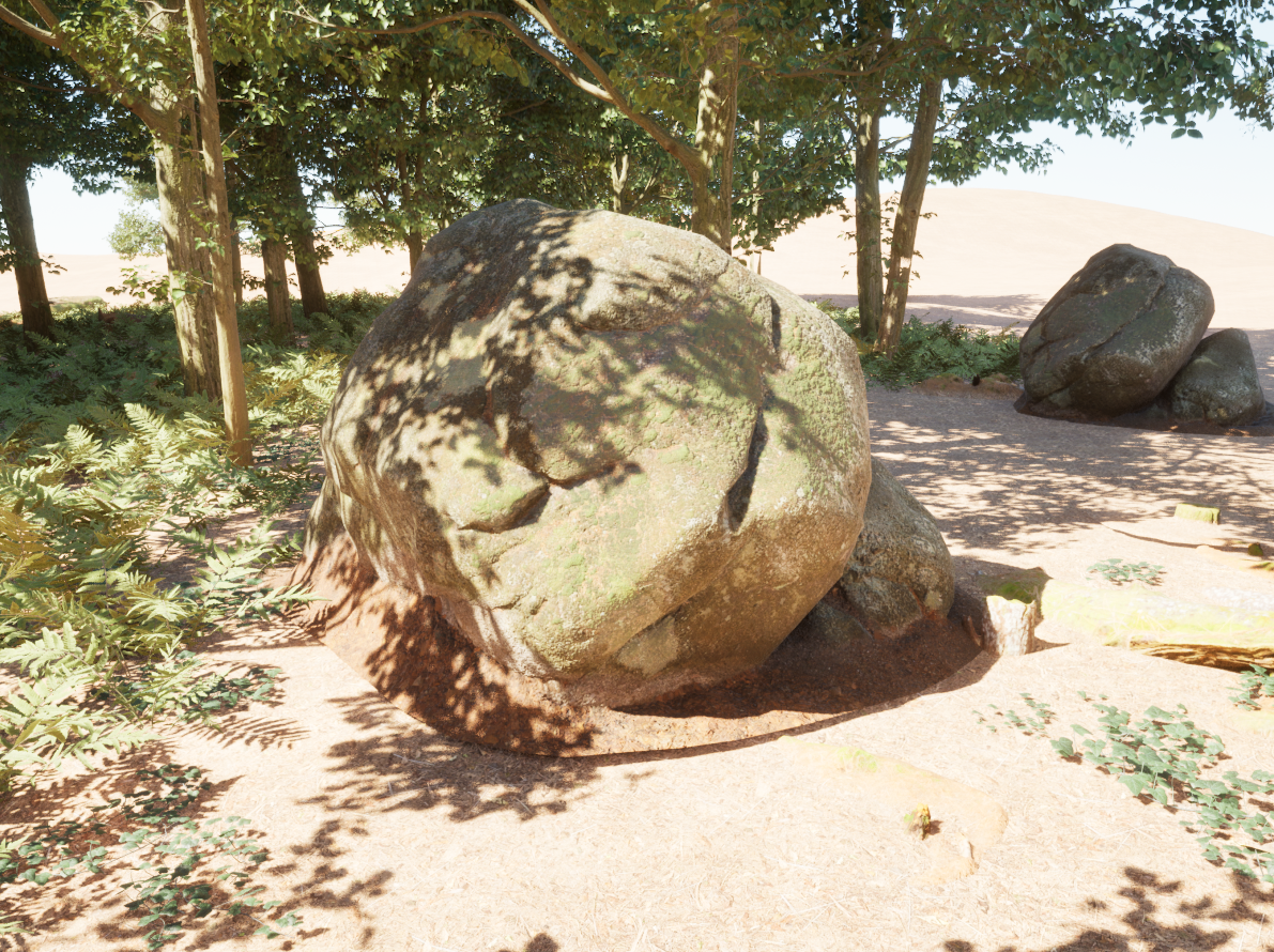
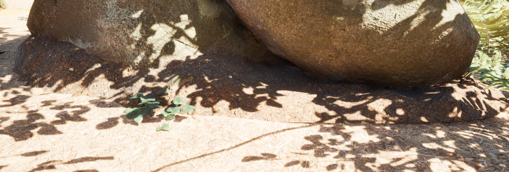
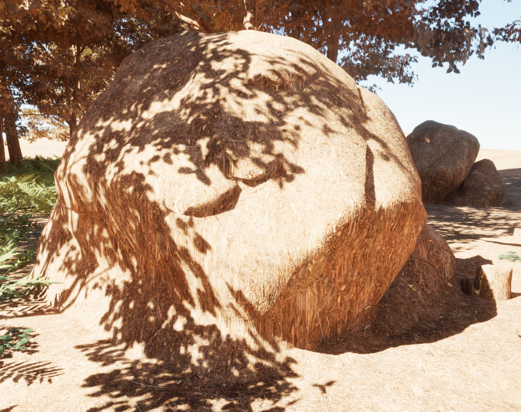
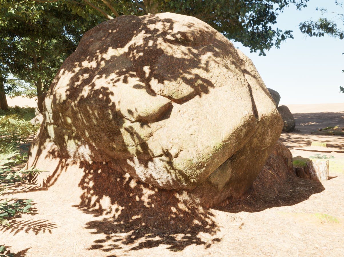
When placing props on a terrain either procedurally, or by hand we may often encounter harsh edges or gaps between an object and the terrain.
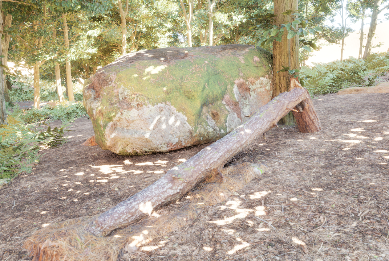
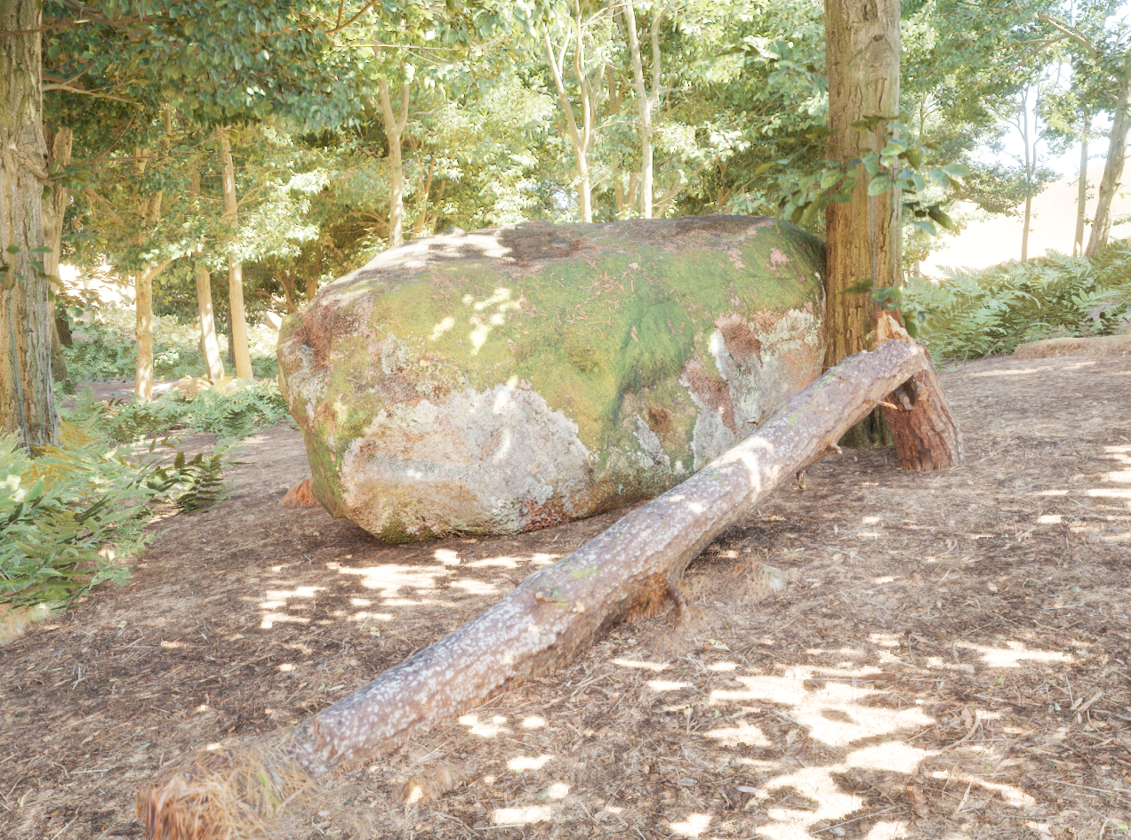
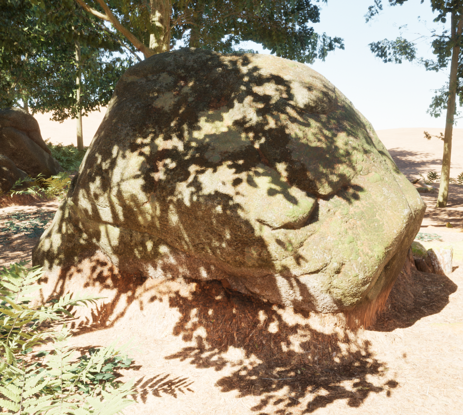
Note how the result looks unnatural even where the boulder megascan intersects the landscape.
It appears the most common (and most straightforward) method for blending props with terrains in Unreal Engine is to get the distance to the landscape via depth fade or distance fields, then use this to control the strength of a dithered pixel depth offset. This is a simple and performant solution, but I find working with distance fields tedious and unpredictable. Furthermore, this issue does not repair gaps between props and landscape.
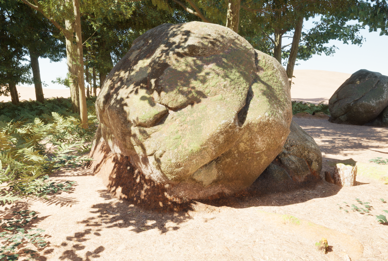
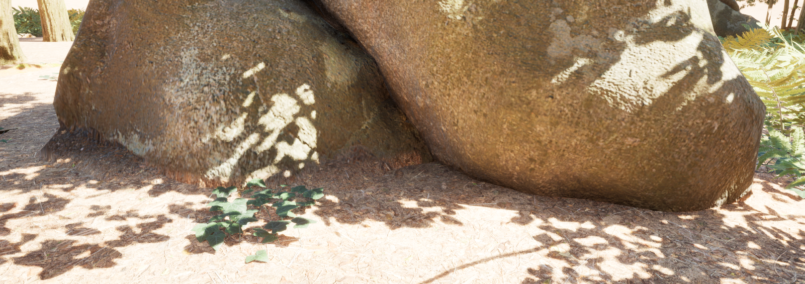
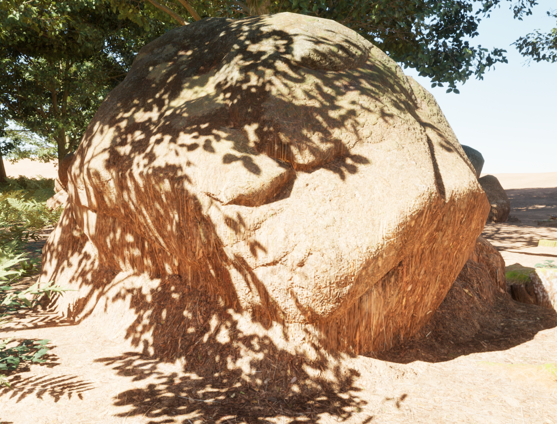
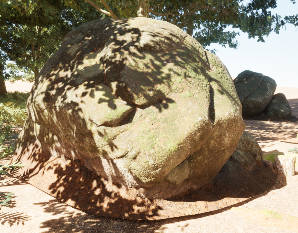
I have therefore written a shader that uses the landscape coordinates to snap prop vertices with the terrain, then directly blend the textures. As you can see in the following images, it has become more difficult to pinpoint where the prop ends and the terrain begins. We also maintain hard edges where the object overhangs or juts straight out from the terrain.
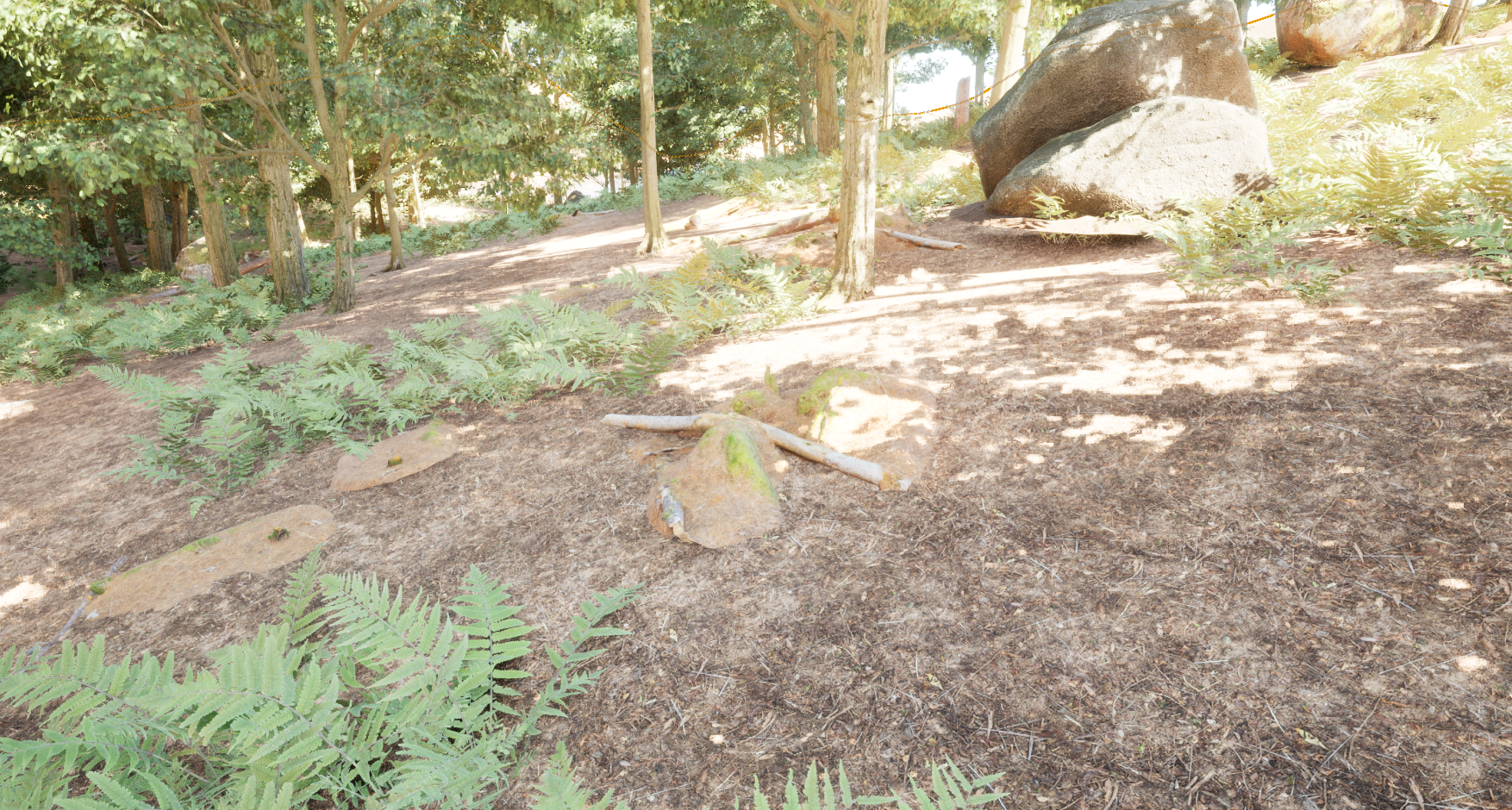
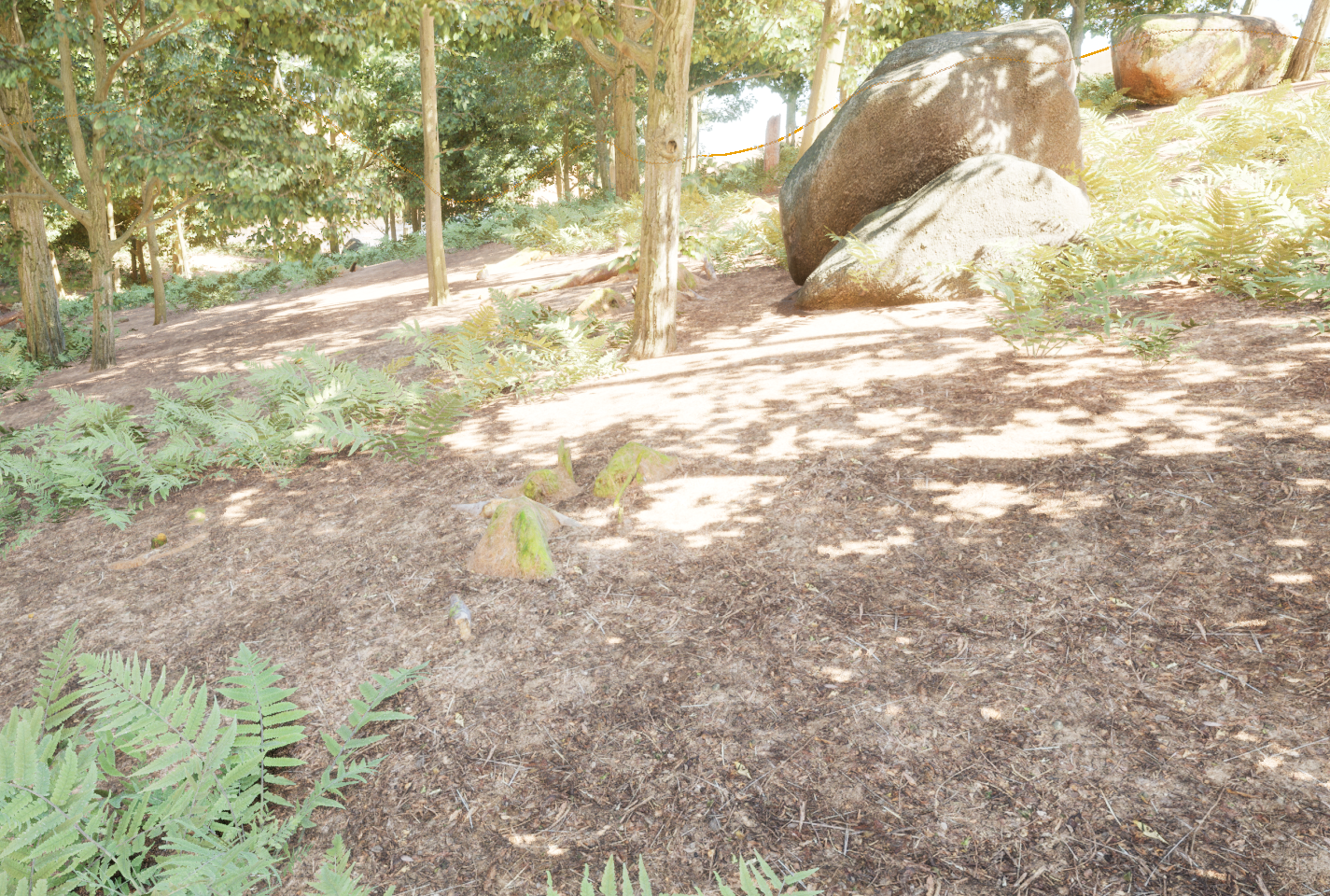
(Note: for the purposes of this demonstration, I have plugged Megascan Assets and Surfaces into a PCG graph to generate this forest.)
Creating The Shader
Getting the Terrain Data
In order to blend and object’s vertices with the corresponding terrain position, we must first devise a method to get the terrain position. Very little landscape data is exposed to in the Material Editor, so we will need to do some manual work to rebuild the information we need.
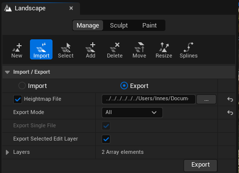
We must first devise a means to get our terrain height data. We cannot directly access the terrain heightmap via the shader, but we can export it from Unreal as a .PNG then reimport it into our project. To do so, we must enter landscape mode, then navigate to the manage tab. Activate the import tab, and under the Import / Export settings ensure that:
- Export is checked
- Heightmap File is checked and set to your project’s content folder path
- Export Mode is set to All Hit export to export your heightmap.
This will export a 16-bit greyscale map that we can reimport into our project via the import button in the content browser. Double-click the imported heightmap to access its settings and ensure the compression settings are set to a linear 16-bit preset such as half float or HDR. This will reduce the rounding errors and eliminate stair-stepping when we rebuild the landscape position data.
Creating the Shader Function
This functionality will likely be used across several materials and shaders, so it is worth separating it out into its own function so we can reuse and update it easily.
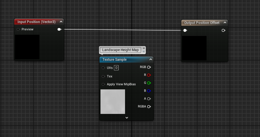
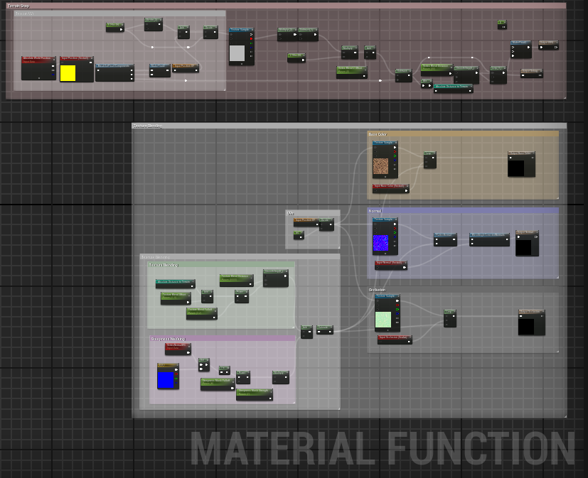
We will start by creating a new Material Function, and naming it MF_TerrainBlend. We will start by creating a single float3 input called Position and a float3 output called World Position Offset. We can also drag in our landscape height map texture.
Parsing the Height Map Data
We currently have a heightmap that contains 0-1 half-float values with 0.5 corresponding to 0 in the Z-axis in world-space. We need to devise a way that we can feed the current XY position into the height map UVs that returns the correct value.
UVs
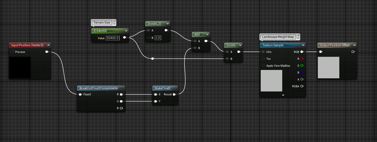
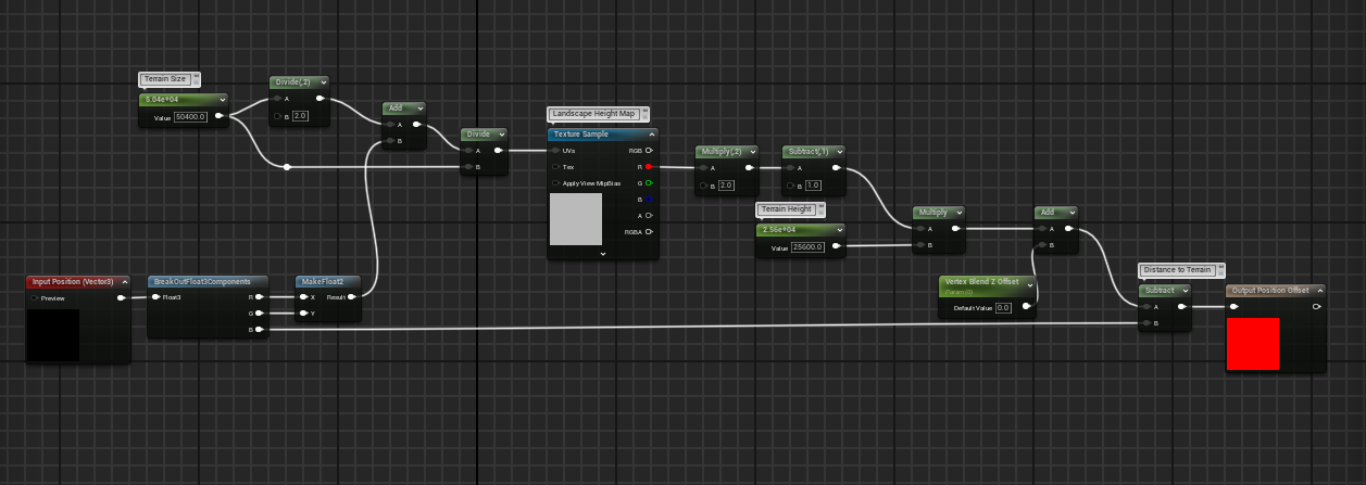
First we will take our Input Position, and break it into it’s 3 components (we will use the Z component later which is why we are not using a Component Mask node). We will recombine the XY components into a Float2. This float2 value allows us to “look down” the Z-axis, which is important when it comes to sampling the UVs. However, this XY value has a range thousands of times larger than the 0-1 range our height map UVs expect, so we need to divide this value by the dimensions of our terrain.
My terrain is 50400 units wide, but this value may differ depending on the settings you used to create your terrain. It is important that you get this value exactly right, as tiny errors will be noticeable. Fortunately, the Unreal documentation contains this useful guide for calculating landscape values: Landscape Technical Guide.
I moved my terrain so that the XY zero point is in it’s center, so I must also calculate an offset to ensure my UVs represent the correct positions. To do this, I simply divided my terrain size by 2, then added it to my XY world position before it is divided by the terrain size.
Terrain Height Calculation
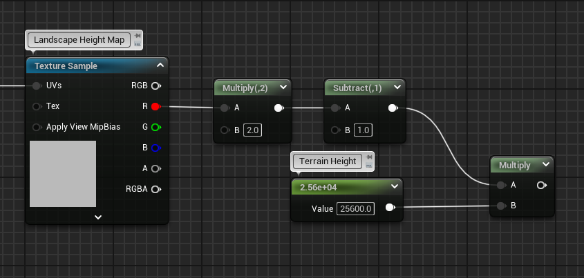
The result of our current graph will offset our assets by a value between 0-1 - which will hardly be noticeable. We need to remap this value, so that we get the entire Z-range offered by our terrain. Since my terrain does not not dip below zero values, I will multiply the texture output R channel by 2, then subtract 1 to give me the full 0-1 range. This value can then be multiplied by the terrain height, which is 25600 in my case.
This gives us the absolute world position of the landscape in the current XY coordinate, but there are still some small adjustments we need to make before this is usable. First of all, we want to tuck the asset vertices slightly below the surface to ensure there are no small gaps when we use our terrain blend. To do this, we can simply create a Z Offset parameter, and add a small value like -5 by default. We also need to calculate the position offset not just the position. To achieve this, we simply subtract our vertex Z position from our calculated terrain height.
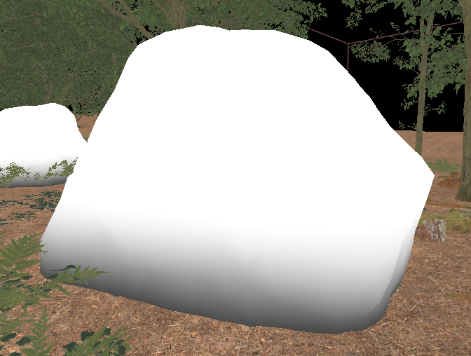
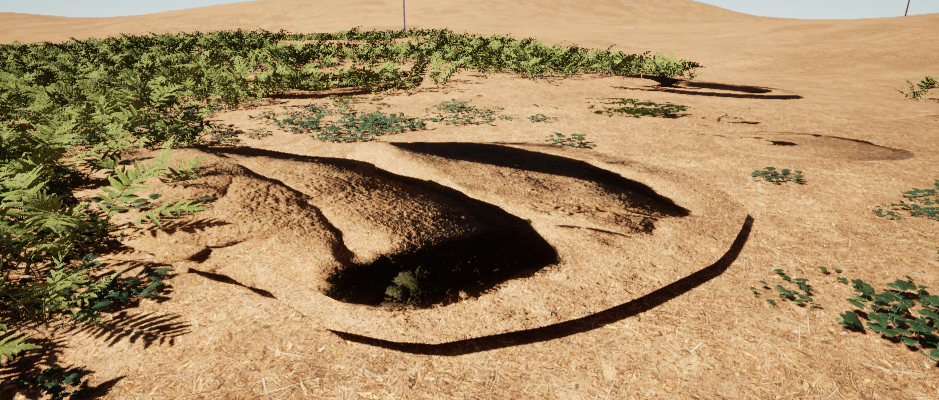
If we plug our function offset into the World Position Offset output in a shader, we should see our assets are now flattened to the terrain. (Note: I added a positive Z Offset to make the rock visible)
Blending
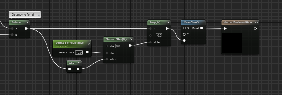
We need to give our vertices a 0-1 value, that determines where it should fall in between it’s usual position, and the terrain’s position. There are many ways we can do this such as using the object-space coordinates or manually painting the vertex colors - but for simplicity, I will just use the distance to the terrain as we already calculated this to produce our world position offset.
We can determine a range that the blend should cover by creating a new float parameter called “Vertex Blend Distance” then plugging that into the Max input of a smoothstep node. This will create a smooth blend from black to white as the vertices move further from the landscape.
We can now plug this smoothstep result into the value input of a linear interpolate node. We will use this value to interpolate between the object’s positions, and the terrain’s positions.
We can see that as we increase the vertex blending distance, more vertices are pulled towards the terrain.
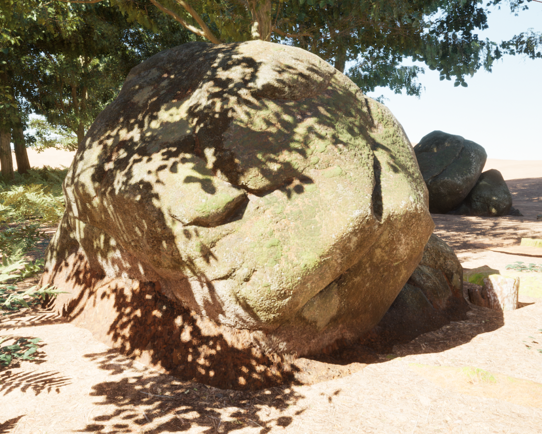
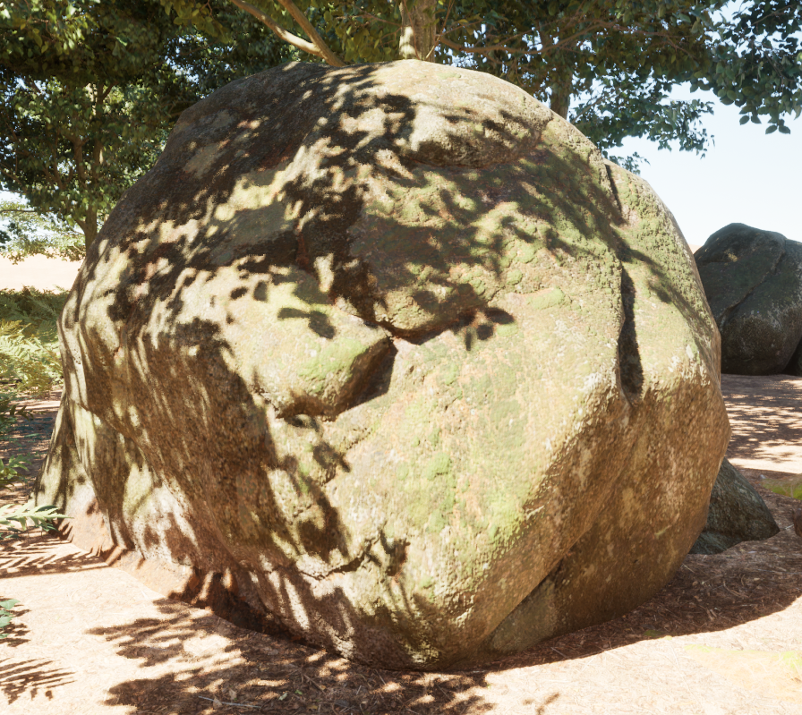
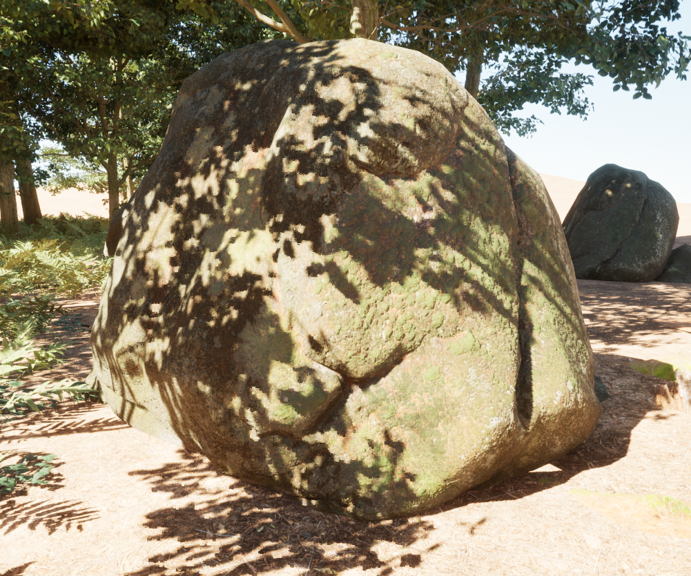
Texture Blending
We still have a sharp edge between the asset and the landscape. Fortunately, these assets will only appear in a specific part of my map where the forest floor textures are used so I can simply resample these textures, and use our previously calculated blend to created a gradual transition between these textures. However, If blending was required for multiple landscape textures, the pixel depth offset method would work better in this scenario.
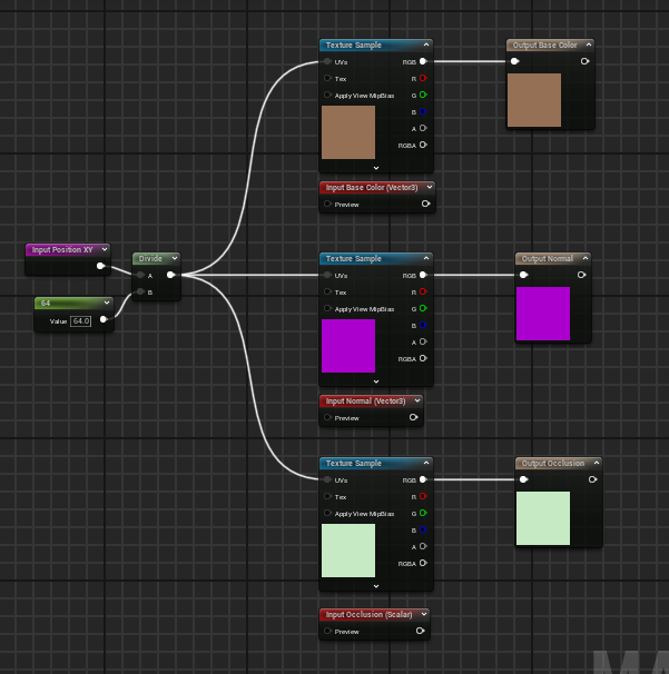
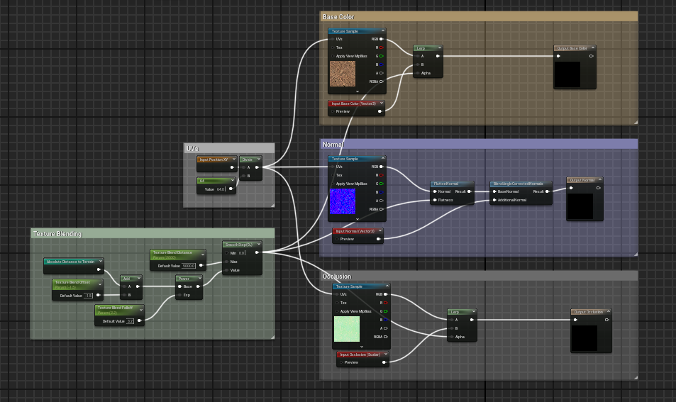
First we must take our Input XY Position and divide it by the number of segments in our landscape (for me this value is 64). We can then use this value as the UVs for our landscape textures. We will also create new inputs and outputs for the PBR values we will blend with the terrain (in my case this is Albedo, Normals and AO).
We can see on prop, that the textures line up perfectly. There is some stretching where the props’ faces are perpendicular to our projection axis, but this will be harder to spot when we apply our blending. Furthermore, we will add a steepness bias to mask out the blending in these areas later in this document.
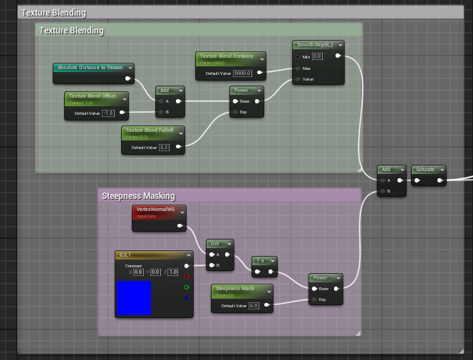
To create our blend, we will take another smoothstep node, and plug a new “Terrain Blend Distance” node to give us the range that the texture blend should cover. The smoothstep’s value input should contain the distance to the terrain we calculated earlier (I created a named reroute node to keep things tidy). We can extend our control over this blending by adding an “offset” parameter to the distance to control how high or low the textures should start blending on our prop, and we can also run a “power” node on this value to control the blending falloff.
We can now use this blend value to lerp between the object’s own textures, and the terrain’s.
We can now adjust our falloff and offset values to control the texture blending.
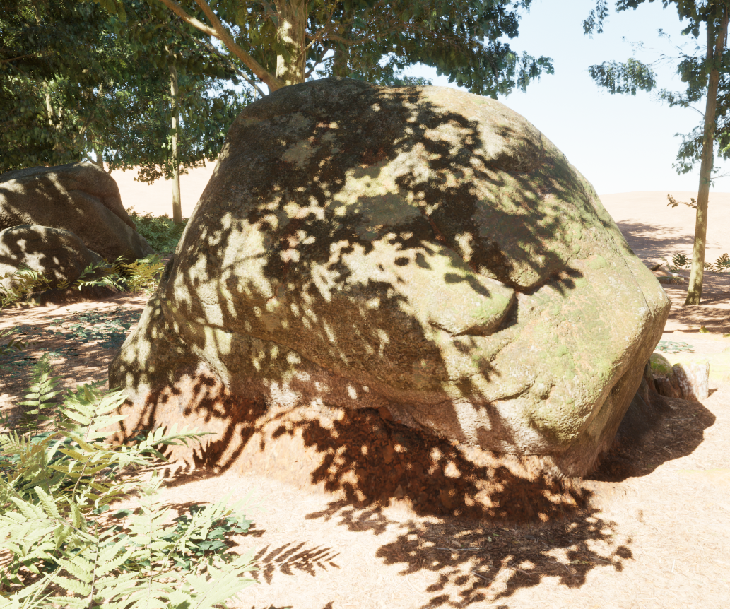
Steepness Masking
We can see that the terrain texture is stretching where the prop’s faces become steeper. We can mask out these steep areas by taking the dot product between the surface normal and the world up vector. This will return a value that is 0 when the face points up, and 1 where the surface is at its steepest. We can make some adjustments to this value, such as strength and falloff, and simply add it to our existing blend value.
We can see that when the mask value is low, we see more of the terrain texture on steeper surfaces.
But when we turn up the masking, steep surface no longer render the terrain texture.
Results
Since we built a shader function, we can slot it in to other existing shaders so we can apply the same blending to a range of assets. This shader works well with procedurally placed assets, as we can rest assured we won’t have any gaps between the content and the landscape. However, in some cases - especially on steep slopes- detail in smaller assets can be lost.
